Peak factor = √2 Average value of rectifier RMS Voltage, V rms = V m/√2 | RMS Current, I rms = I m/√2Ĭenter tap rectifier, Transformer utilization factor (TUF) = 0.693īridge rectifier, Transformer utilization factor (TUF) = 0.812 Hence, in both half cycles the load resistance has the same direction of the current.Īverage voltage, V average = 2V m/π | Average Current, I average = 2I m/π The biasing of the diodes alternates in each half cycle and creates a same polarity across the load.


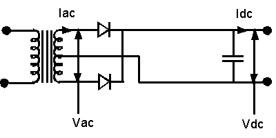
Current flows through D4, load resistance and D1. Similarly, on the negative half cycle (A- Negative & B- Positive) diode D4 & D1 is in forward biased. D1 & D4 are in reverse biased, thus the conduction path forms through diode D2, load resistance, and diode D3. On the positive half cycle, (A- Positive & B- Negative) diode D2 & D3 are in forward biased. The bridge rectifier has an advantage over the center tap, that is it works without a center tapped transformer or a common ground. Because in a center tap rectifier the transformer winding should consider separately. The efficiency, ripple factor, average value, RMS value all are same except the transformer utilisation factor(TUF). From a center tap rectifier, the bridge rectifier has a difference only in the circuit arrangement. The bridge rectifier consists of 4 diodes in a bridge circuit configuration. Because the load is always on half of the secondary winding. In the center tap rectifier, the output DC voltage will be half of the total output voltage of the secondary winding. The biasing of diodes changes alternately with respect to change in the polarity of terminals. Current flows through D2 and load resistance, from the B terminal to the center tap of the transformer. On the negative half cycle (A- Negative & B- Positive), the diode D2 is forward biased and diode D1 is reverse biased. Hence the current flow through D1 and the load resistance, from terminal A to center tap. On the positive half cycle (A- Positive & B- Negative), the diode D1 is forward biased and diode D2 is in reverse biased. The center tap act as a common zero potential terminal in both half cycles.
FULLWAVE BRIDGE RECTIFIER CALCULATOR FULL
Full wave center tap rectifier circuitĪ center tapped full wave rectifier works only with a center tap transformer or with a similar common potential point across the terminals. Both positive and negative half cycles of the AC signal is converted to a unidirectional flow of current. It converts the complete cycles of the AC signal to DC. Peak factor = 2 Full Wave rectifier theory Transformer utilization factor (TUF) = 0.287 Rms Voltage, V rms = V m/2 | Rms Current, I rms = I m/2 So the polarity of the output terminals keeps unchanged and obtains a unidirectional current through the load.Īverage voltage, V average = V m/π | Average Current, Iaverage = I m/π And on negative half cycle (A- Negative & B- Positive), the diode will be reverse biased and prevents the current to flow in the opposite direction.

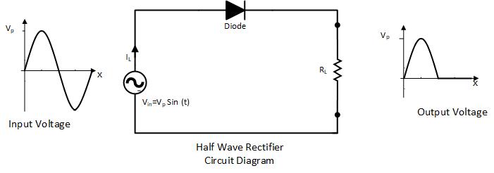
Thus it utilizes only the one-half cycle of the input signal.ĭuring the positive half cycle (A- Positive & B- Negative) of the signal, the diode will be forward biased and conducts the current through the load resistance.

Half Wave rectifier theoryĪ half wave rectifier clips the negative half cycles and allows only the positive half cycles to flow through the load. It can be done by either blocking the reverse flow of current or by redirecting the reverse flow to one direction. In simple words, a rectifier converts the bi-directional flow of current to a unidirectional flow, which maintains a constant polarity across the load. Where an Alternating current periodically changes its direction of the current, that is an alternating polarity at the terminals.Ī rectifier is a circuit that converts AC to DC and this conversion process is called rectification. Direct current flows only in one direction, which means it has a constant polarity across its terminals.


 0 kommentar(er)
